
Introduction
Here’s a simple truth to start: fast charging rises and falls on the power stage. An EV charger power module sets the pace for speed, uptime, and cost—no more, no less. Picture a busy highway stop as a cold front rolls in; cars queue, cables stiffen, and the site lead watches the dashboard for temperature and fault lights. In many regions, operators say station performance swings most when the power modules struggle with heat and grid noise, not the cars themselves. So, what should we measure, and how do we compare modules without getting lost in lab charts (you bet, there are plenty)?
We’re going to walk through what really changes outcomes on the ground: how modules handle partial-load efficiency, how they shed heat, and how they ride through faults. Then we’ll compare old approaches with new design principles. The goal is simple. Fewer surprises. More miles. Ready to dig in? Let’s move to the next layer.
Legacy Limits: Where Traditional Designs Fall Short
Why do legacy designs stumble?
Older stacks often chase peak kW on paper while ignoring daily duty cycles. Look, it’s simpler than you think. Many chargers sit at 20–60% load for most hours. If a module uses a dated rectifier and a basic PFC stage, it sheds efficiency right where it matters. That extra heat stresses the thermal management path and pushes fans harder. Add in high ripple on the DC link, and you get uneven stress on power converters downstream. Over time, that means early wear, random trips, and a hit to uptime when the queue is longest—funny how that works, right?
There’s more. Legacy topologies built on IGBTs can run fine at nameplate, but they often struggle with high ambient temperatures and quick transients from the grid. Harmonic distortion spikes, CAN bus chatter grows, and protective limits kick in. Single-point cooling plates and tight airflow channels become hot spots instead of heat sinks. When a fault hits, the unit may lack modular redundancy or clean fault isolation, so the whole cabinet derates. Field techs then spend time chasing heat-soaked parts rather than swapping a clean, hot-pluggable unit. The pattern is clear: weak partial-load performance, brittle thermal paths, and thin fault containment drive most of the pain.
Next-Gen Principles That Raise the Bar
What’s Next
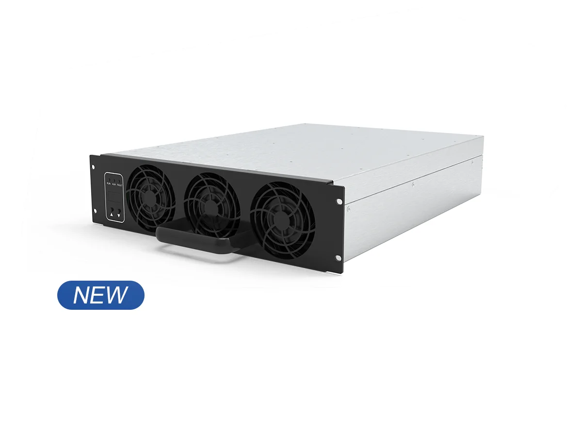
Modern designs flip the script with a few core ideas. Start with wide-bandgap switches like SiC MOSFETs, then add interleaved totem‑pole PFC and soft‑switching in the isolation stage. That cuts switching loss, lowers EMI, and keeps the DC bus clean. Next, use smart thermal design—heat pipes, even pressure on cold plates, and segmented airflow—to move heat out fast. Finally, add digital control loops and edge computing nodes to tune behavior in real time. This is where a high protective charging module stands out: it holds efficiency across partial loads, rides through grid bumps with better PFC response, and isolates faults so the rest of the stack keeps working. Different day, different weather—same stable output.
Compared with the legacy path, these principles mean smoother current sharing, cleaner telemetry, and faster service. Fewer hot spots, fewer nuisance trips, and longer life for capacitors and magnetics. We’ve moved from “survive the peak” to “excel in the middle,” which matches real station behavior. To choose well, use three simple metrics. First, verify partial‑load efficiency at 30–60% with inlet air above 35°C; that’s your real-world burn rate. Second, check thermal headroom and derating curves—flat curves mean stable uptime. Third, demand fault isolation and fast module swap time, measured in minutes, not hours. Keep it friendly, keep it measurable, and your sites will thank you. For deeper specs and practical considerations, see winline EV charger.