
Data-first lead: why this comparison matters now
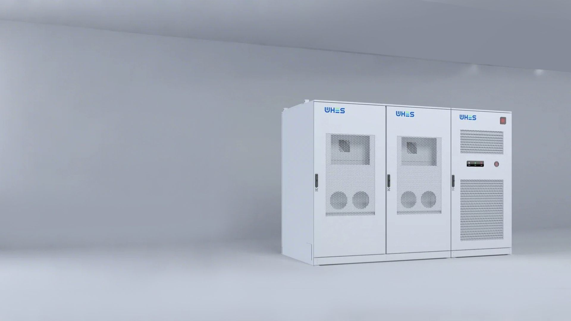
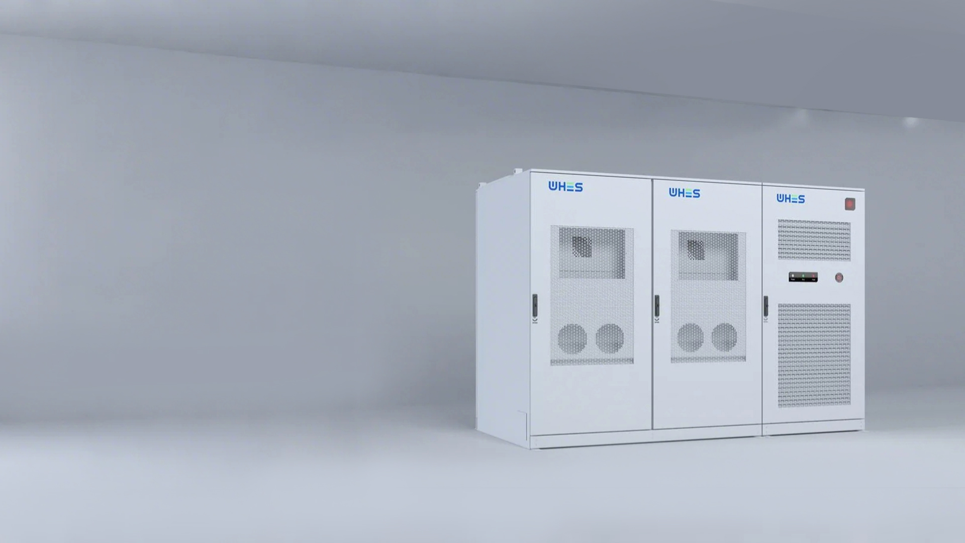
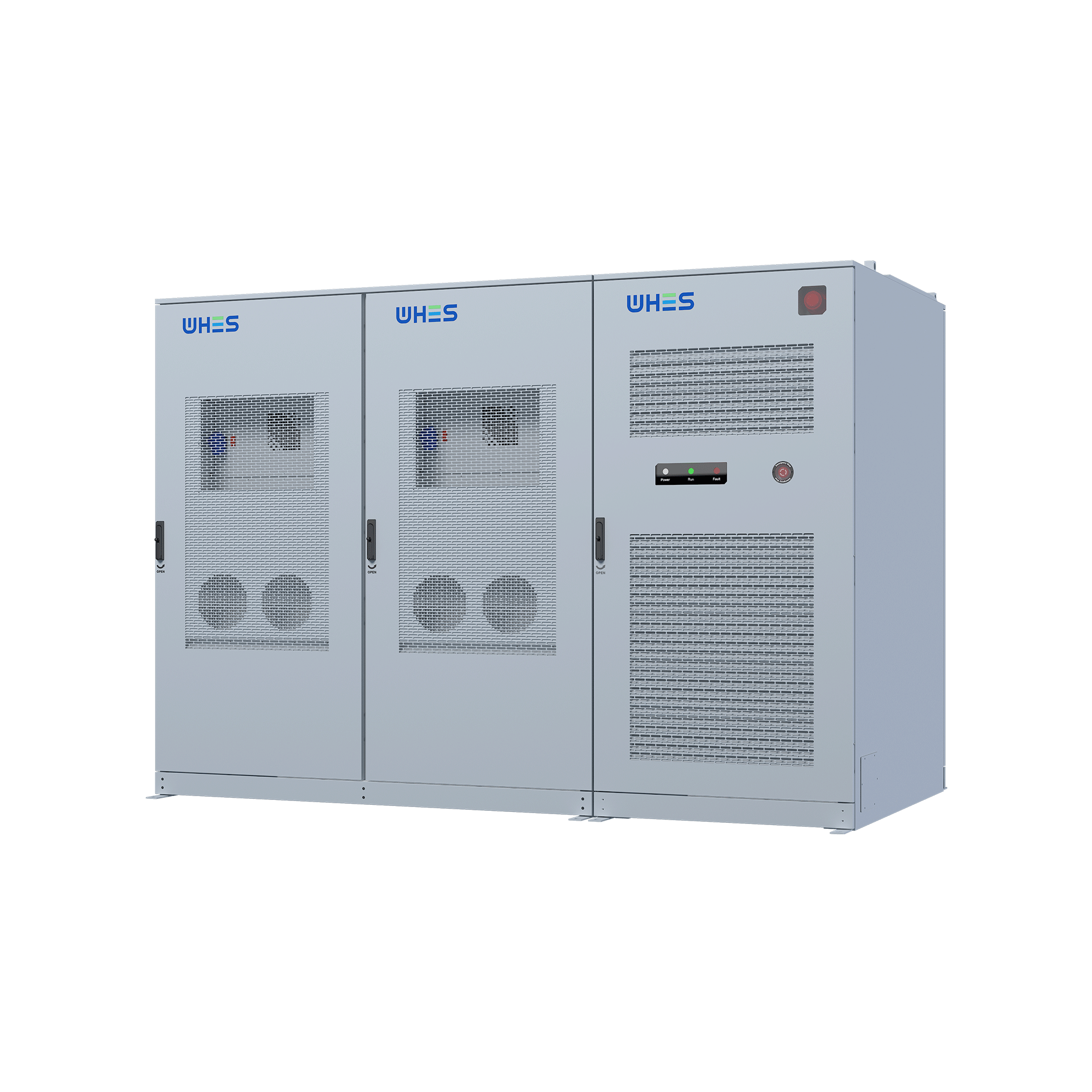
Grid operators increasingly measure reliability at a fine timescale — seconds and milliseconds — because transient voltage and frequency excursions can cascade into outages. This article uses empirical metrics to compare how Lithium Iron Phosphate (LFP) cells, when deployed in factory-direct commercial energy storage and paired with robust controls, reduce those micro-disturbances. For practitioners specifying systems, two concrete product references help ground the discussion: a factory-packaged commercial energy storage module and integrated commercial solar battery storage systems that are common in C&I projects.
What “photonic-level” disturbances mean for C&I sites
Photonic-level grid disturbances is shorthand for very short-lived anomalies (sub-second voltage sags, fast frequency deviations) that can trip sensitive loads or plant PLCs. For facilities with precision manufacturing, data centers, or critical chillers, these blips drive production loss and protective trips. The measurable outcomes to track are ride‑through time, voltage-recovery profile, and event‑based cycle impact on the battery system’s state-of-charge (SoC).
LFP stability: the metrics that predict field reliability
Evaluate LFP on three key dimensions: cycle life, thermal stability, and charge acceptance. LFP chemistry typically delivers higher cycle life and a flatter discharge curve than many alternatives, which translates into predictable inverter behavior during short bursts of discharge. From a control perspective, a high-performing Battery Management System (BMS) and conservative depth-of-discharge settings reduce risk of premature degradation — and they enable rapid cell balancing during frequent micro-events.
Factory-direct C&I systems: why integration reduces disturbance exposure
Factory-direct units arrive with pre-validated thermal management, matched inverter firmware, and standardized communications. That reduces field commissioning errors and mismatched control loops that can amplify grid noise. In practice this means fewer firmware incompatibilities between BMS and energy management systems (EMS), faster commissioning, and a unified warranty path — all of which reduce time-to-stable operation and lower operational risk.
Real-world anchor: grid stress cases and what they taught us
Major events — for example, the heatwave-driven capacity strains that prompted rolling outages in California over recent summers — pushed operators to procure fast-response storage to smooth short-duration peaks. Those deployments demonstrated that systems optimized for rapid response and high cycle durability mitigate cascading trips more effectively than ad-hoc battery arrays assembled on-site. The lesson: validated, factory-integrated systems shorten the feedback loop between deployment and measurable grid improvement.
Comparative data: LFP vs. other chemistries on transient response
When comparing chemistries for transient suppression, consider charge/discharge acceptance (C-rate), internal resistance, and thermal margin. LFP tends to exhibit lower internal resistance stability over life, enabling consistent high-C discharge for short durations without heat spikes. NMC variants may offer higher energy density but can show steeper impedance rise as they age — which affects inverter control during rapid, repetitive events. For micro-disturbance suppression, predictability often beats peak energy density.
Operational design points to verify with vendors
Ask for measured performance, not claims. Key items:
- Short-duration power throughput curves at relevant SoC bands (showing C-rate behavior).
- BMS telemetry schema and failure-mode behavior (how it handles cell imbalance and thermal derating).
- Factory test reports for thermal runaway mitigation and enclosure ingress protection.
Also verify integration testing with your site’s inverter and EMS — synthetic tests that emulate repeated sub-second events reveal control-loop interactions you won’t see in single-shot stress tests. —
Common specification mistakes and how they increase disturbance risk
Typical errors include under-sizing usable capacity (too-aggressive DoD limits), specifying incompatible communication protocols between inverter and BMS, or omitting thermal margin for hot climates. These mistakes create situations where the battery either refuses to respond during a disturbance or responds unpredictably. The fix: model frequent-event cycling over expected duty cycles and require vendor-provided life prediction under that specific duty.
Three golden rules for selecting the right C&I storage
1) Prioritize predictability over peak specs: favor chemistries and systems with consistent impedance and documented cycle-life under your expected duty cycle. 2) Require factory integration evidence: demand end-to-end test results (BMS + inverter + EMS) that mirror your transient scenarios. 3) Insist on measurable acceptance criteria: contractually bind ride-through time, voltage-recovery profiles, and telemetry access for post‑commissioning validation.
Implementing those rules favors factory-direct, LFP-based systems because they align chemistry stability, thermal design, and control integration into a predictable product. In the market that reliability equates to lower downtime and clearer lifecycle economics — which is the practical value WHES brings to projects. WHES. —