
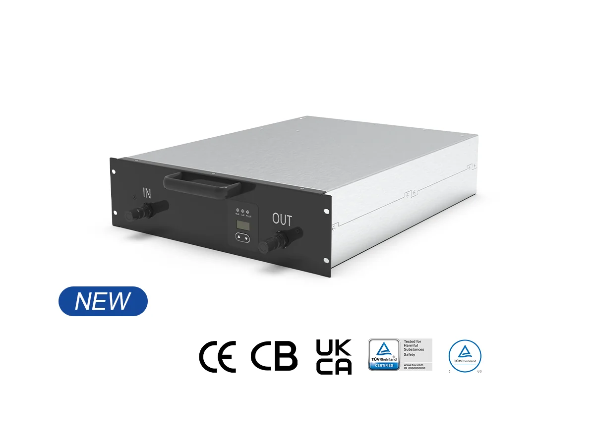
Introduction: When Heat Turns Fast into Slow
Let’s start clean: fast charging is a thermal game before it’s a power game. A liquid cooling module sits at the heart of that game, whether you notice it or not. Picture a rainy night on the M25. Chargers are humming, queues are growing, and logs show 20–40% derating once heat stacks up—funny how that works, right? The high frequency charging module runs at high switching speeds, so heat density spikes in the IGBT stack and across the DC bus. If the path from heat source to coolant isn’t tight, you lose power, uptime, and trust. Look, it’s simpler than you think: poor thermal paths starve throughput, and users blame the site, not the silicon.
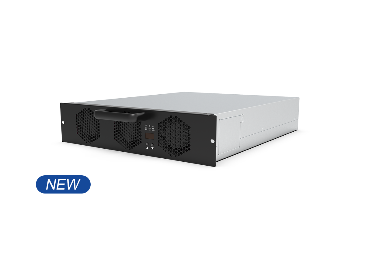
Here’s the bit folks skip (have a butcher’s): traditional air-cooling looks cheap, but the fans fight head-on with dust, salt fog, and cramped cabinets near power converters. Edge computing nodes at the site need steady temps to keep telemetry honest; hot air means noisy data and jittery control loops. Air gaps grow, seals age, filters clog. Then the coolant? In many air-first designs there isn’t any, so heat has one route—out, slowly. Result: throttling, hot spots, and rising MTBF risk. So the deeper flaw isn’t just airflow; it’s mismatch between heat flux and the path out. We need a design that carries heat away at source—tight cold plates, short loops, and smart manifolds. Right, on to the comparison.
Comparative Insight: Why Liquid Paths Win When Power Peaks
Air-cooling moves bulk air; liquid paths move heat. Under 20–40 kW module loads, switching edges raise local heat flux faster than fans can clear it through fins. Liquid cold plates clamp onto the die-side thermal interface, so the gradient from junction to coolant is short and predictable. That means fewer derates during midday spikes and less thermal cycling across busbars. With liquid cooled ultra-fast charging, you get stable outlet temps, smoother PWM control, and quieter harmonic behavior on the DC bus—even as ambient swings. Air still has a place for the cabinet, sure, but not as the primary path at high density. And when you mix in sealed loops, corrosion inhibitors, and quick-connects, maintenance drops—by design, not by hope.
Real-world Impact
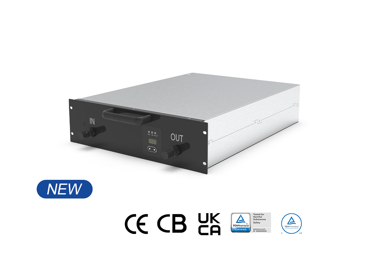
Field teams see it first: fewer power converters tripping on overtemp, steadier session times, calmer users. A compact coolant manifold lets you pack more modules in the same footprint without turning the cabinet into a wind tunnel. Diagnostics improve too; sensors on inlet/outlet temps tell you if a cold plate degrades, before it bites you. Compare that to filter changes, fan curves, and hot recirculation zones—air gets messy fast. With liquid cooled ultra-fast charging, the thermal map flattens, so your derating curve shifts right. More hours at full tilt. More predictable revenue. Less noise—literally and figuratively. And once you scale, standardizing on loop geometry makes spares simple—funny how standard parts become strategy, right?
Take this as a short playbook: evaluate solutions on three metrics. 1) Thermal resistance from junction to coolant (K/W), measured at peak load with verified delta-T. 2) System derating profile vs ambient, including cabinet effects and coolant flow (not just lab numbers). 3) Service model: mean time to swap a module, bleed a loop, and validate sensors. Nail those, and your site runs cooler, longer, and with fewer surprises. Same amps, smarter path. For balanced guidance, keep sharing field data, stress the edge cases, and choose partners that design for heat first. That’s how a site stays proper in all seasons—and that’s the honest graft from winline technology.