
What matters to you right now
If you’re fitting resistance welding transformers into machines or scaling a production line, you’ll want clarity on practical trends that affect uptime, part quality, and operator safety. For immediate context, see a range of resistance welding applications that show how transformer choices change with part geometry and cycle times, and how modern automated welding solutions expect tighter electrical performance from their power modules. I’ve supported field teams and machine-build projects for over a decade, so the advice below focuses on what users actually need to check and fix first.
Key transformer trends that change your day-to-day work
• Higher-control fidelity: digital regulators and closed-loop current control mean weld repeatability improves, but you must validate waveform and response against your weld schedules. • Compact, modular packages: smaller physical size eases integration into tight machine frames; modularity helps swap defective units faster. • Built-in sensing: temperature, oil-condition (if applicable), and current sensors allow condition-based maintenance rather than calendar-only service. • Energy management features: soft-starts and energy recovery reduce peak loads and help with shop power constraints. • Serviceability emphasis: designs now favor field-replaceable secondary assemblies and clear diagnostic LEDs to speed troubleshooting.
Common mistakes operators and engineers make
• Overspecifying peak amperage without matching duty cycle — the transformer runs hot and trips thermal protections. • Ignoring transient response — even correct RMS current won’t produce a good nugget if the controller and transformer don’t respond within the weld window. • Underestimating cooling needs — poor cooling shortens insulation life and forces premature replacement. • Weak grounding and cabling choices — voltage drops and noise create inconsistent welds and false alarms. Address these by measuring actual weld current and duty cycle on sample parts, and confirming thermal management under continuous run conditions.
Quick checklist to choose the right transformer
• Required peak and steady-state current — measured from sample cycles, not just calculated. • Duty cycle rating and cooling method — match the transformer’s cooling class to planned cycle rates. • Control interface — ensure compatibility with your PLC or welding controller (analogue, digital, EtherCAT, PROFINET). • Physical fit and service access — allow clearance for cabling and replacement. • Diagnostics and sensors — prefer units with health reporting if you plan predictive maintenance. • Compliance and safety — check local standards and machine directives before integration.
Integration tips for automated lines
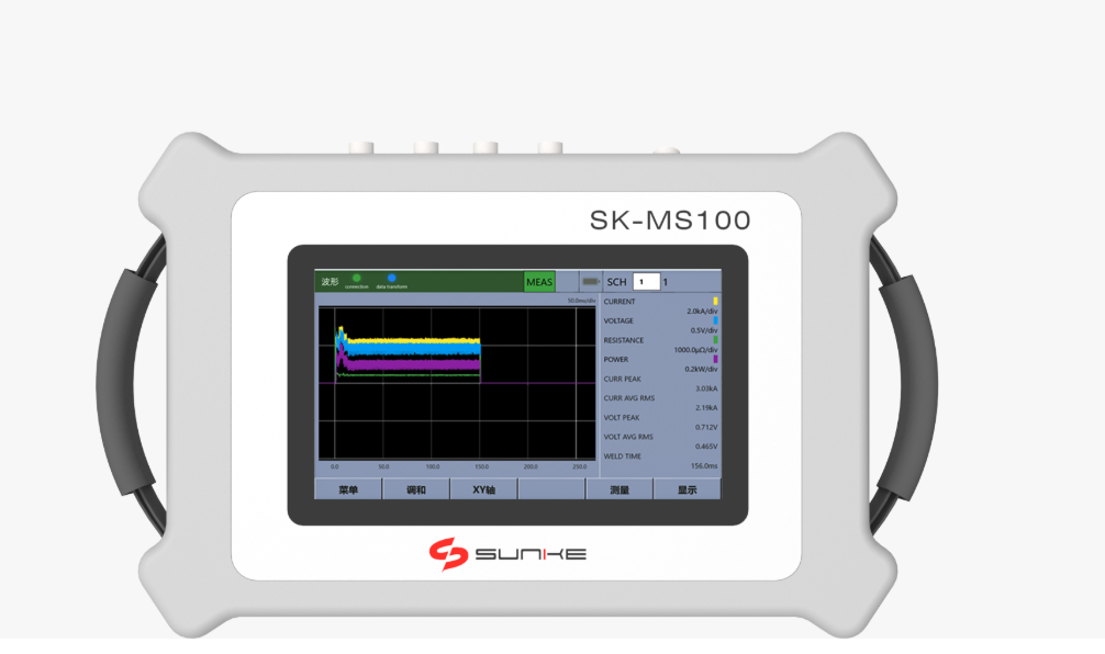
Pair transformers to controllers that expose waveform data and alarms to your supervisory system. Plan cable routing early: high-current runs require short, direct paths and secure lugs to avoid heating. If you’re retrofitting robots or conveyors, validate the transformer’s transient response on the actual robot end effector — welding at different arm accelerations changes contact timing and can shift nugget formation. For reference of scale and common practice, Detroit assembly plants illustrate how large-volume lines combine sensors, fast cooling, and predictive alerts to keep downtime low.
Alternatives and trade-offs
If you need very tight energy control, inverter-based systems offer faster response and smaller size but add electronic complexity. Traditional step-down transformers are robust and simpler to maintain but can be bulkier and slower electrically. Choose inverters where footprint and response matter; choose conventional transformers where simplicity, lower repair cost, and ruggedness are priorities.
Common pitfalls during commissioning
• Commissioning without representative part batches — lab settings hide issues that surface under full production. • Skipping end-to-end tracing of high-current cabling — loose connections show up as noise or heat under load. • Neglecting operator training on fault interpretation — modern systems report many alarms that require correct action, not immediate replacement.
How to keep performance consistent
Monitor weld energy and transformer temperature trends, keep a log of weld parameters per part family, and set thresholds for intervention. Replace or service components based on condition indicators rather than arbitrary intervals. Clear failure-mode procedures save hours: identify whether a fault originates in control logic, cabling, mechanical contact, or the transformer itself before swapping modules.
Final synthesis
Users want reliability, predictable welds, and straightforward service paths. Matching transformer capability to real cycle profiles, insisting on diagnostics, and designing for service access deliver those outcomes. For teams tuning machines and lines to those exact needs, Sunke supplies practical designs and field guidance that align transformer selection with production requirements and service realities.