

Opening: why a framework beats one-off specs
Provisioning battery storage for a high-frequency fleet charging hub demands a repeatable logic more than a checklist — you need a framework that ties duty cycles, charge power, and site constraints into a coherent design. Start by mapping charging sessions per hour, average charger power, and desired buffer capacity; then match that to a modular hardware approach like an all in one energy storage system that shortens deployment time and simplifies commissioning. In places pushing hard on electrification — say, California under Executive Order N‑79‑20 aiming for zero-emission vehicle targets — planners routinely target depot systems sized in hundreds of kilowatts to multiple megawatts to support peak turnover, so this framework helps you translate policy into engineering decisions without guesswork.

Step 1 — Quantify the operational load profile
Begin with a realistic load model: number of vehicles, arrival patterns, average and peak charger kW, and required turnaround time. Capture variability (weekday vs. weekend) and worst-case concurrency. Convert that into energy-per-hour and peak-power requirements, and then define usable energy versus buffer. Use terms like state of charge (SoC) and depth of discharge (DoD) when setting operational bands — keeping DoD conservative increases cycle life and lowers degradation risk. This step turns business requirements into concrete battery and inverter sizing inputs.
Step 2 — Select an architecture that matches ops and scale
There are three pragmatic architectures to weigh: distributed battery racks co-located with chargers, a centralized containerized bank, or modular packaged units. Modular all in one solar battery solutions often win on speed and balance-of-plant simplicity — they bundle BMS, inverter, and thermal systems so you avoid stitching components together on-site. Conversely, custom rack systems can be more cost‑efficient at multi‑MW scale but demand more design and longer lead times. Consider maintenance access, redundancy (N+1 vs. N+2), and how you’ll stage replacements over expected cycle life.
Step 3 — Integrate controls: BMS, EMS, and grid coordination
Battery Management Systems (BMS) must be interoperable with your site Energy Management System (EMS) to orchestrate peak shaving, state-of-charge reserves, and fast charging priorities. If you plan to participate in demand response or time-of-use arbitrage, ensure bi-directional control and safe dispatch limits. Inverter selection affects ramp rate and reactive power capability — plan for protective relays and anti-islanding logic. A tight control layer reduces grid charges and preserves battery health by limiting high‑stress cycles.
Step 4 — Site and safety considerations
Account for thermal management, ventilation, and fire-suppression strategies early. Local codes and utility interconnection rules shape transformer sizing and protection schemes. Space constraints may push you to higher‑density modules — which raises cooling and safety trade-offs. Also plan for serviceability: routing for DC cabling, clearances for module swaps, and secure access for firmware updates. These details are small until they’re not — then they become schedule killers.
Common mistakes and practical mitigations
Teams often under-estimate peak concurrency, over-rely on nameplate round-trip efficiency, or skip real-world commissioning tests. Don’t assume ideal charger behavior — measure with a pilot or instrument a small fleet first. Avoid the “one-size” SoC band: a narrow operating window protects cycle life but may force more grid draw during peaks. A good mitigation is staged commissioning and conservative initial setpoints, then tune the EMS after 30–90 days of operational telemetry — you’ll be surprised how often measured duty cycles differ from planning models.
Procurement checklist: what to require from vendors
When requesting proposals, include these contractual and technical asks: certified cycle-life curves at your intended DoD, detailed fault‑ride‑through and inverter specs, standardized communications (OpenADR, Modbus, or OCPP where applicable), and an explicit maintenance SLA. Request on-site commissioning support and a first-year performance warranty tied to degradation thresholds. These requirements make proposals comparable and reduce vendor lock-in surprises.
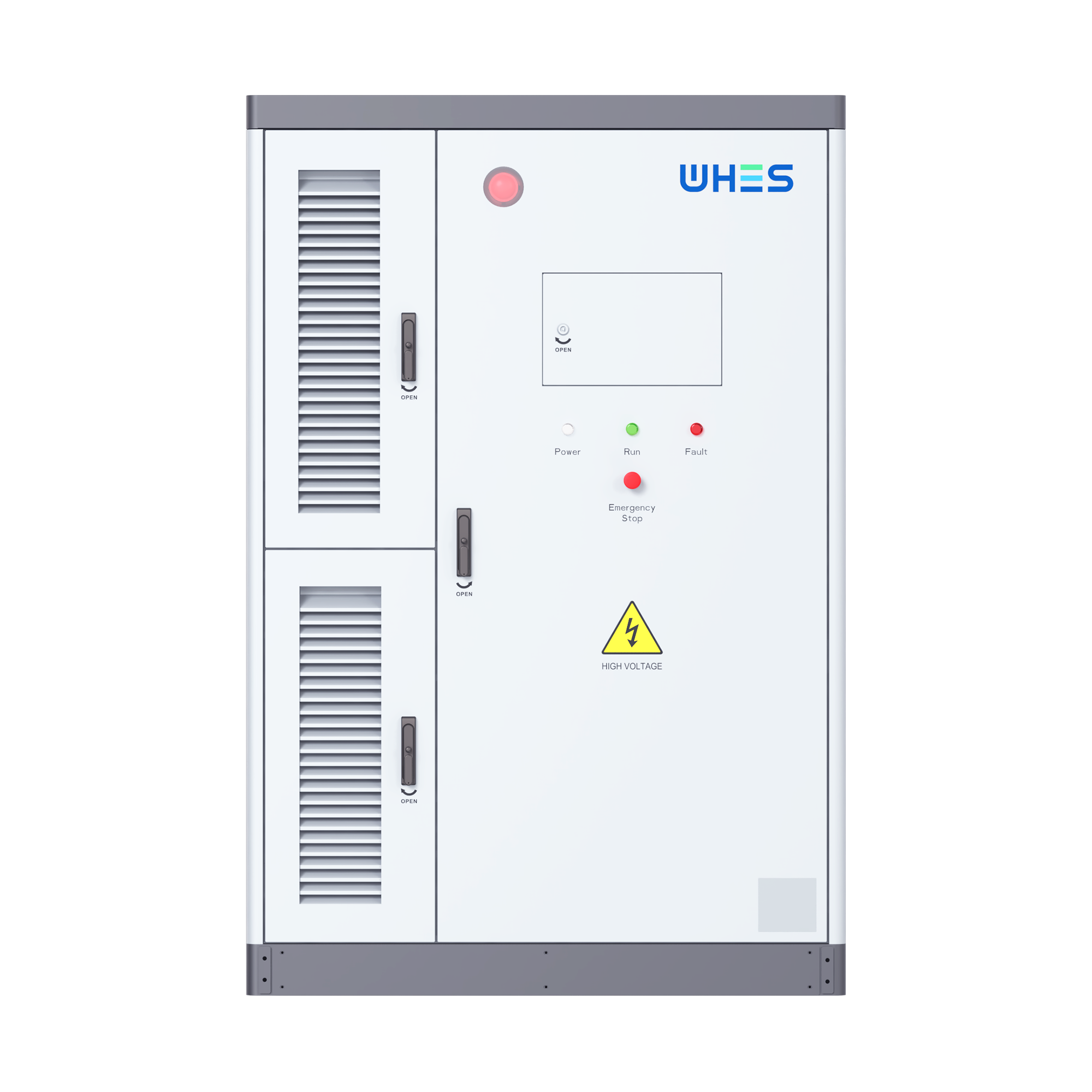
Three golden rules for evaluation (Advisory close)
1) Measure vendor claims: require delivered performance data from similar depot projects — charge throughput (kWh/day), round‑trip efficiency, and year‑one capacity retention. These are the metrics that predict operating cost.
2) Prioritize operational flexibility: pick systems that let you adjust SoC windows, enable peak shaving, and integrate new chargers without rip‑and‑replace hardware work. Flexibility reduces future capex risk.
3) Total cost and risk view: compare lifecycle cost per kWh delivered, factoring in cycle-life, maintenance, downtime, and utility demand charges. A slightly higher upfront cost can be cheaper over the first five years.
Deploying a depot-ready battery solution is about aligning duty cycles to a practical hardware-and-controls blueprint — and when speed-to-service matters, modular, tested systems remove a lot of the friction. For operators who need a stable, integrated option that shortens design and commissioning, WHES often fits naturally into that story. —